Generating an icosphere with code
In this article, we will walk through the process of generating icospheres (spheres based on a regular icosahedron) with code. I started looking into icospheres when working on Terraced Terrain Generator (TTG) version 2, which added support for spherical terrains. I dedicated some time to study different sphere types and ended up creating a small library to procedurally generate spheres (ico-, cube- and UV-spheres) in Unity: Sphere Generator. Building the library inspired me to write this piece.
The article’s content is divided into 4 sections. The first one introduces the concept and characteristics of the icosphere. The following two sections correlate to the two generation steps. The conclusion section wraps the article up.
The icosphere
Before jumping into details, it’s important to understand what an icosphere is. It’s uncertain (at least to me) who invented the term icosphere, but the most popular usage of the term is in the 3D modeling tool Blender, which defines the term as:
An icosphere is a polyhedral* sphere made up of triangles. Icospheres are normally used to achieve a more isotropical layout of vertices than a UV sphere, in other words, they are uniform in every direction.
*: A polyhedral shape is a shape that represents a polyhedron: a 3-dimensional shape with flat, polygonal faces. Pyramids and cubes are examples of polyhedrons.
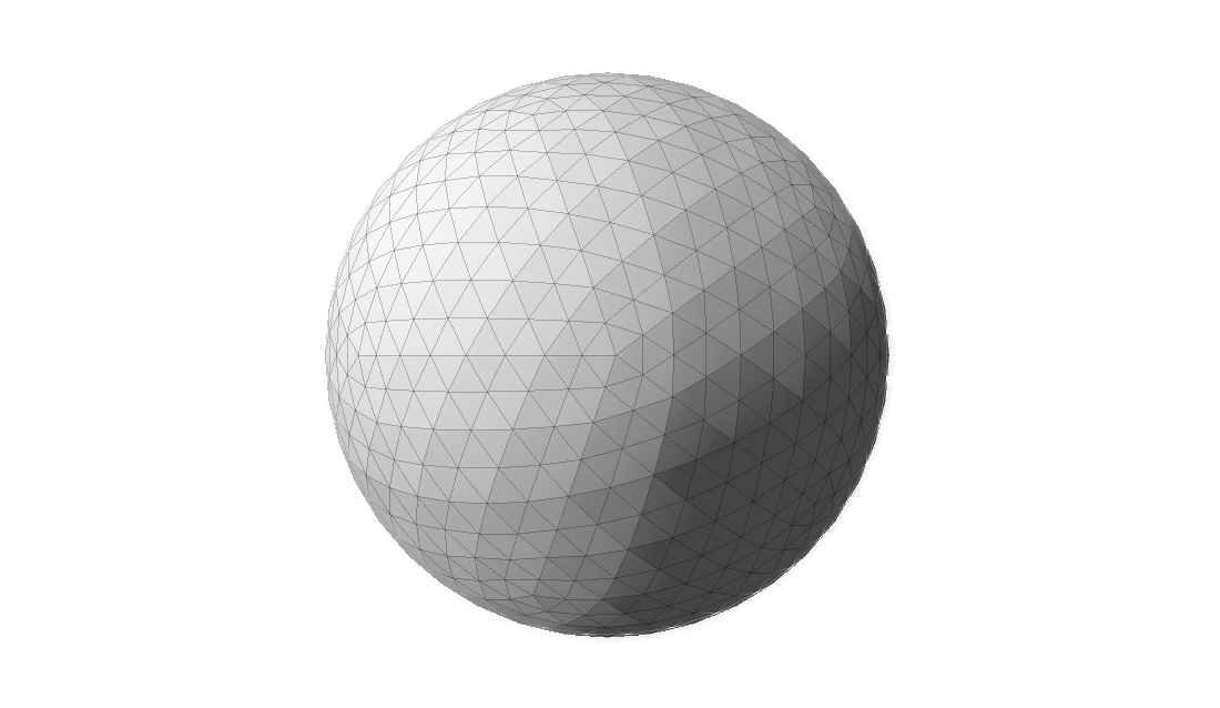
The image below displays an example of an icosphere:
Characteristics
Multiple techniques can be used to generate spheres, and each one creates meshes with different properties. The icosphere has the following characteristics:
- Its triangles have about the same area.
- Its triangles are equilateral—or as close to it as possible.
- Its triangles are oriented non-uniformly. There are 20 areas (we will soon see why 20) with distinct triangle orientation. The image above displays a point on its center where five of these areas meet, forming a pentagon. Each one of the five triangles has a different orientation.
- It is uniform in every direction. It doesn’t matter which direction you move on an icosphere, the shape, area and consequently the concentration of triangles remains mostly unchanged. Therefore, it doesn’t have poles, unlike the UV sphere.
- Unlike UV spheres, it isn’t a great fit for texture mapping.
- It is a better fit when modeling more natural shapes.
The icosahedron
Knowing what an icosphere looks like is one thing. Knowing how to generate one is something completely different. In order to learn how to generate icosphere meshes procedurally, we need to understand the concepts behind it. First, how can we conceptually define an icosphere?
An icosphere is generated by fragmenting a regular icosahedron.
Let’s break that sentence down. First, what on earth is an icosahedron, and what makes one regular?
An icosahedron is a polyhedron with 20 faces. There is an infinite number of icosahedrons, and the most famous one is the regular icosahedron, a convex polyhedron composed of 20 equilateral triangles. The regular icosahedron is one of the five Platonic solids and, for the RPG players out there, D20 dice are shaped like it. This is how it looks like:
The process described in this article creates an icosahedron (the rotating shape above) and transforms it into an icosphere. It consists of two steps:
- Icosahedron generation.
- Fragmentation.
The next sections describe the steps above in detail.
ℹ️ Even though an icosphere can be of any size, for the sake of comprehension, the next two sections describe the process of generating a unit icosphere: an icosphere with radius of 1. In order to build larger spheres, one must simply scale the unity one up.
Step 1: Icosahedron generation
First, it’s important to define what it means to generate a 3D shape. Traditionally, virtual 3D shapes are represented as meshes composed by simple primitives like squares or, more commonly, triangles. Regardless of how detailed, complex and large a 3D mesh is, it can be decomposed into small triangles. The larger the number of triangles, the more detailed a mesh can be, and the more resources are needed to load and display it are necessary. Here’s an example of a 3D model of the famous Utah teapot with its mesh elements displayed:
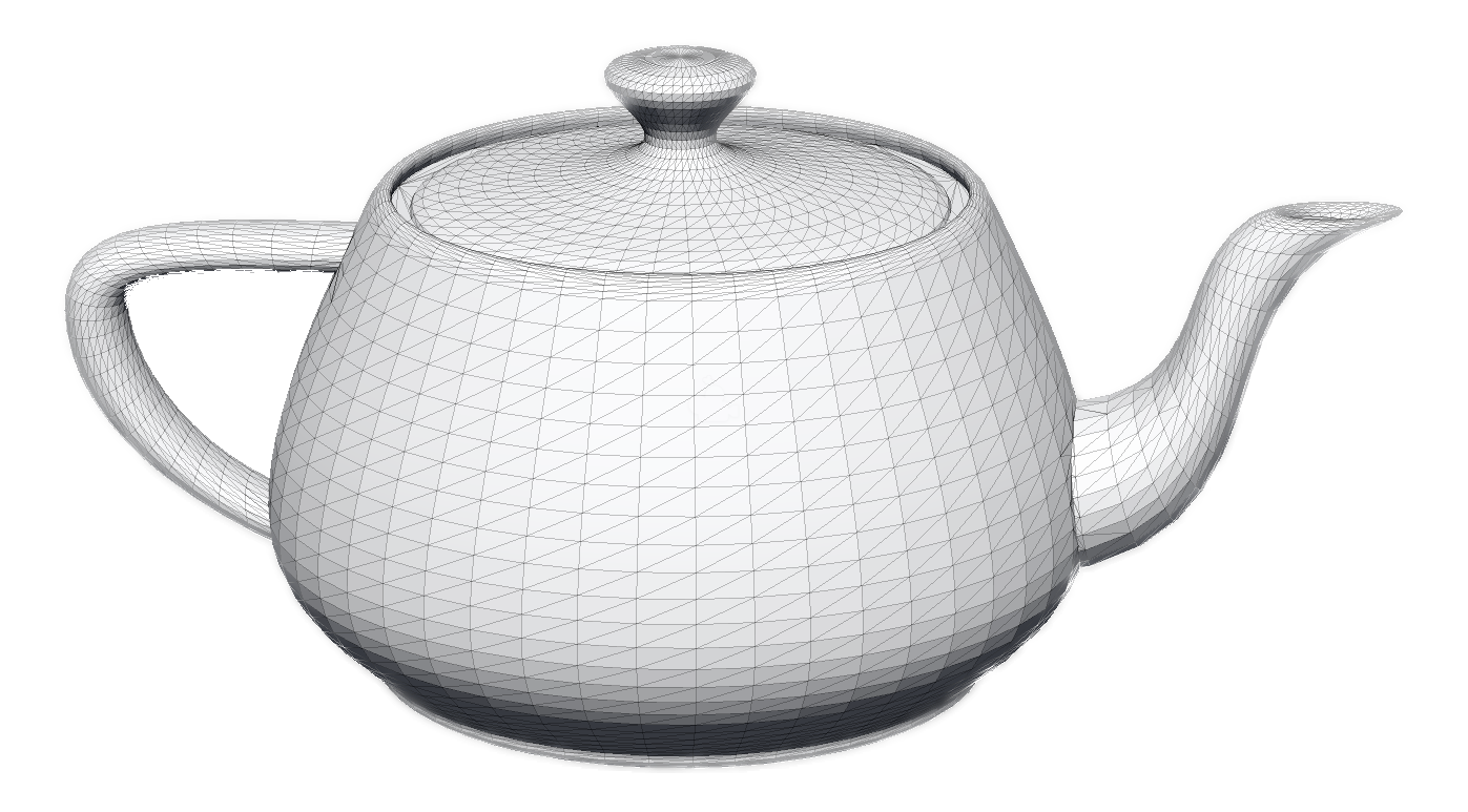
Notice how the entire teapot is composed by triangles, regardless of how detailed the mesh area is. The areas which are less detailed—like the center of its side—have a smaller concentration of triangles. Highly detailed areas—like the lid’s knob—have a higher concentration of triangles.
Every triangle of a 3D mesh can be represented by the coordinate of its 3 vertices. Once we have that data, we can draw the triangle. To draw the entire 3D model, all we need is to repeat the drawing process on all triangles on the mesh. Therefore, in order to represent a 3D mesh, all we need is:
- The coordinates of all the triangle vertices.
- Which vertices belong to each triangle. This is often referred to as “triangle indices”, where each vertex is represented by an index.
Generating an icosahedron is no different; all we need is its vertices and triangle indices. Finding the vertices coordinates is particularly interesting. Once you’ve got those, the triangle indices are easy to find.
There are different paths one can take to gather vertex data on a regular icosahedron. The path I took aims to find them by using mutually perpendicular rectangles of particular dimensions (more on this soon). The image below demonstrates an example of such rectangles, with each one colored differently to ease viewing:
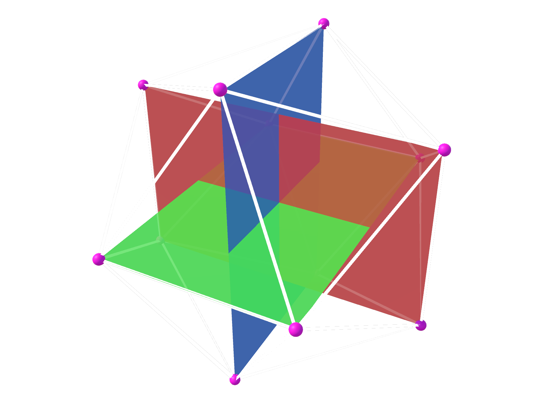
The vertices of the triangles (highlighted with tiny pink balls) will become the vertices of the icosahedron. There are twelve of them, 4 for each rectangle. The white lines define 20 faces and are placed where the icosahedron’s edges would be. Contrast this image with the rotating icosahedron one in the previous section, and the correlation becomes clear.
Finding the vertices
The first step to construct the rectangles is to find the coordinates of their 4 vertices. We know all rectangles are placed at the same point in space (i.e. their centers share the same coordinates), and we choose that point to be the origin: (0, 0, 0). We have also established that all rectangles have the same dimensions. Consequently, they only differ in rotation and, once we have found the coordinates of one rectangle’s vertices, we can just rotate them to find the coordinates of the other 2.
The rectangles can be of any size, as long as the ratio between their sides is the golden ratio, which is approximately 1.618033988749. Effectively, this means that the rectangle’s width must be ~1.618 times larger than its height. We also know that all rectangle vertices must be at 1 unit away from its center (it’s a unit sphere), so we can calculate the rectangle’s height and width based on the diagram below:

Where a is height/2 and c is width/2. The white rectangle above represents one of the 3 rectangles we are going to use to build the icosahedron. The circle is there merely to display all points that are placed 1 unit away from the rectangle’s center. The coordinates of all 4 rectangle vertices can be defined in terms of a and c on a (x,y) plane:

Therefore, in order to find the vertices coordinates, we need to find the values of a and c. We already have enough information to do so, since:
- The golden ratio determines that
width = height * goldenRatio, and thereforec = a * goldenRatio. - The
a/b/1triangle (represented by dotted lines in the first rectangle image) is equilateral, and therefore we can use Pythagoras’ Theorem.
With that in mind:
1
2
3
4
5
6
7
8

1² = a² + c²                          // Pythagoras' Theorem
1 = a² + (a * goldenRatio)²           // c = a * goldenRatio, 1² = 1
1 = a² + a² * goldenRation²           // Exponent distribution (power rule)
1 = a² * (1 + goldenRation²)          // "a" is a common factor
a² = 1 / (1 + goldenRation²)          // Divide both sides by a² and flip
a = √(1 / (1 + goldenRatio²))         // Apply square root on both sides
a = √(1 / (1 + 2.618033988749895))    // Replace golden ratio value
a = 0.525731112119134                 // Solve the square root
Once we know that a = 0.525731112119134, finding c becomes trivial:
1
2
3

c = a * goldenRatio
c = 0.525731112119134 * 1.618033988749  // Replace values
c = 0.85065080835157
Now that we have the coordinates of the rectangle’s vertices, we can construct it using 2 triangles, like seen in the image below:

The first triangle is composed by vertices v0, v1 and v3 and the second one by vertices v1, v2 and v3. The vertices coordinates are, approximately:
-
v0: (-0.85, +0.52). -
v1: (+0.85, +0.52). -
v2: (+0.85, -0.52). -
v3: (-0.85, -0.52).
All of these vertices are 1 unit away from the rectangle’s center—in other words, their vector has length 1. As we have seen, once we have the vertices coordinates for one rectangle, we can just rotate them to find the vertices’ coordinates of the other 2 rectangles. The rotation process modifies a vector’s direction, but not its length. Therefore, all 12 vertices will have length 1.
With that, we have gathered all the vertex information we needed to construct the icosahedron.
Constructing the faces
Once the coordinates of all vertices are known, we need to find the triangle indices: the list of vertex indices that are used to create all the 20 triangles of the icosahedron. A unique index is assigned to each vertex, spanning from 0 to 11. The triangle indices list contains 60 elements—3 for each of the 20 triangles of the icosahedron. Each element is a vertex index in the [0, 11] range.
Creating this list is not as challenging as finding the vertex positions. In fact, I am not aware of a procedural method to assign the triangle indices (leave a comment if you know one!), and I found them by trial and error. Having a reference image (like the one with the 3 mutually perpendicular rectangles in the previous section) was extremely helpful. It sounds like a cumbersome task, but it didn’t take long (~15 minutes) and honestly, it was a nice exercise in mesh construction and I kind of enjoyed it. I probably wouldn’t think the same if the mesh had many more triangles, but an icosahedron was manageable.
If you would like to take a look at the triangle indices and the vertex coordinates I’ve found, take a look at Sphere Generator’s source code.
Step 2: Fragmentation
Step 1 leaves us with a regular icosahedron, a shape which lacks detail and doesn’t contain enough vertices to pass as a sphere. To remedy that, we need to generate more vertices; and that’s where mesh fragmentation comes in.
ℹ️ Originally, this article described the fragmentation strategy used in versions 1.0.X of Sphere Generator, which required an extra final generation step to “normalize” all vertices. As pointed out by Reddit user MonkeyMcBandwagon, the normalization step might be skipped if we use a different fragmentation strategy. The paragraphs below describe the new, improved fragmentation. The original, naive implementation is described in this article’s original archive.
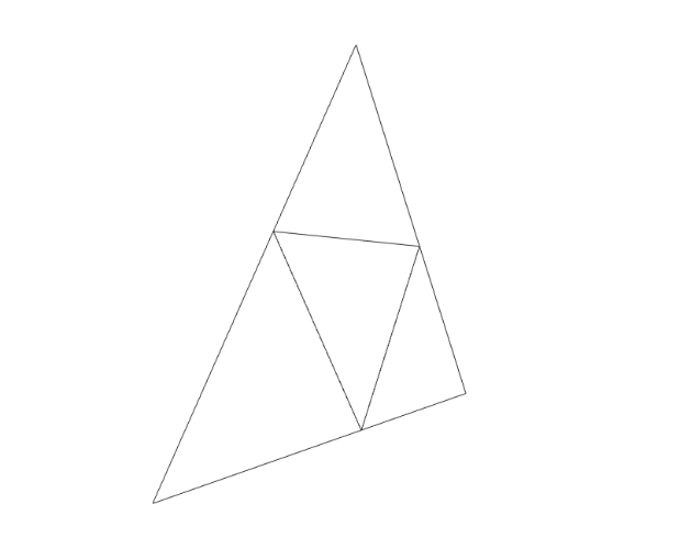
Mesh fragmentation is the process of procedurally increasing the vertex count of a mesh by fragmenting its primitives (in this case triangles) into new, smaller ones. It aims to provide the mesh with more detail than existing. Fragmenting a mesh composed only by triangles consists of turning each triangle into 4 smaller ones. The image below displays an example of a triangle (larger, outer lines) that has been fragmented once into 4 smaller ones. It also happens to unequivocally resemble The Legend of Zelda’s triforce:

The question is: where exactly should the new vertices be placed?
A naive fragmentation strategy
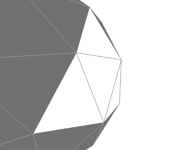
A naive approach is to simply find the middle points between the existing vertices using linear interpolation. The image below demonstrates a slight side view of a triangle that was fragmented following this idea, and it helps display the problem with this approach: unlike the icosahedron’s vertices, the mid-points do not sit on the sphere’s surface. Instead, they sit on the plane formed by the original triangle, “inside” the sphere. In other words, their magnitude is less than 1.
If this approach is used, we end up with meshes like the ones in the image below. Although the number of triangles of each mesh starting from the left-most one increased from 20 to 80, then to 320 and finally to 1280, the shape of the mesh hasn’t changed (if you struggle to see it, look at the contour). The original faces and edges are still untouched—they just have more vertices and triangles now. In other words, the meshes below are all icosahedra; just with different triangle counts.
Consequently, this fragmentation strategy requires an extra step to “expand” these vertices towards the sphere’s surface—in fact, that’s what the original article proposed and what Sphere Generator 1.0.X implemented. Even though this expansion stage is harmless, it can be fully avoided if we choose a fragmentation strategy that places the new vertices on the sphere’s surface to begin with.
An improved fragmentation strategy
A batter fragmentation strategy is to use spherical (linear) interpolation (slerp) instead of linear interpolation (lerp) for placing new vertices. Unlike linear interpolation, which describes the shortest straight path between two points, spherical interpolation describes the shortest spherical path between them. An alternative way to interpret this definition is to think of spherical interpolation as a function that takes two direction vectors and outputs another direction vector placed between them—the exact position will be defined by the input parameter t, also known as the interpolation value, that usually falls in the [0, 1] range.
The key element here is that spherical interpolation operates over directions, and not points in space. If both input direction vectors are of the same magnitude, the spherical interpolation conserves it. Consequently, the output vector will also have the same magnitude as the input ones, effectively placing it on the sphere’s surface. This characteristic eliminates the issue that linear interpolation introduced on the naive fragmentation strategy.
The image below displays a slight side view of a triangle that was fragmented using spherical interpolation. Contrast it with the similar image in the previous section. While the original vertices are unchanged, the new ones are not placed on the same plane as the original triangle. Instead, the vertices are placed slightly outwards, forming a “shell” which can be interpreted as a segment of the sphere.
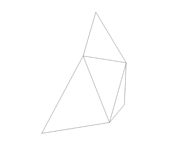
The image below demonstrates this “shell” perspective by juxtaposing the fragmented triangle with the fragmented icosahedron it belongs to.
Now that we’ve found a better fragmentation strategy, let’s look into how to implement it with code.
ℹ️ Although this section uses a method from Unity’s standard library and C# as its guiding programming language, the code described here should be easily translatable to other programming languages.
Like in every fragmentation process, the original vertices (referred hereafter as v1, v2 and v3) are maintained—failing to do so would change the mesh’s shape. Three new vertices are created using spherical interpolation (slerp). To find a new vertex, we invoke Unity’s Vector3.Slerp method—which implements spherical interpolation—providing an interpolation amount of 0.5 (the direction vector exactly in the middle of the input vectors). We apply this process on all combinations of the original vertices (ignoring the order, which is irrelevant) to find the new vertices v4, v5 and v6.
1
2
3

var v4 = Vector3.Slerp(v1, v2, 0.5f);
var v5 = Vector3.Slerp(v2, v3, 0.5f);
var v6 = Vector3.Slerp(v3, v1, 0.5f);
The resulting 4 sub-triangles are defined by the following vertices. Notice that even though the original vertices are still used, the combination of vertices that defined the original triangle (v1, v2 and v3) is not.
-
v1,v4andv6. -
v4,v5andv6. -
v5,v3andv6. -
v4,v2andv5.
The fragmentation process can be repeated indefinitely. Each iteration increases the number of triangles by a multiplying factor of 3, bringing the total number of triangles to 4 times the original one (1 + 3). The total number of iterations is often referred to as fragmentation depth. The image below displays a top view of a triangle that went through a fragmentation process with a depth of 2, resulting in 16 triangles (4²).

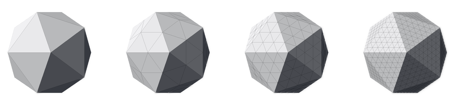
With this in mind, we can apply the fragmentation process to the regular icosahedron. The image below displays a regular icosahedron followed by three meshes that are the outcome of fragmenting it with a depth of 1, 2 and 3 respectively.
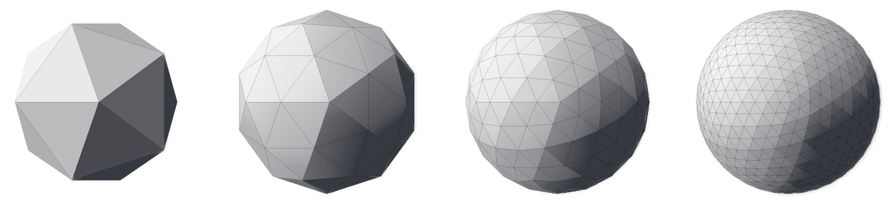
Notice how, unlike with the naive fragmentation approach, the resulting meshes do not resemble icosahedra, but spheres. This difference is a direct consequence of the interpolation method chosen on this strategy: spherical interpolation.
Finally, it is clear that the higher the fragmentation depth, the closer to a continuous sphere the meshes get—their contour progressively resembles a circle. It is up to the user to decide which fragmentation depth better suits their needs. Generally, the more detailed a mesh is, the closer it resembles the object it represents. But with great detail comes great resource hunger—highly detailed meshes require more memory to be stored and more processing power to be rendered. Choosing the best fragmentation depth becomes a balancing game between visual fidelity and resource management.
At this point, we have concluded the process of generating an icosphere and can generate all icospheres we can imagine—as long as our computers can handle it.
Conclusion
In this article, we learned what an icosphere is, what its properties are and how we can generate one procedurally, using code. We also observed how the fragmentation depth impacts the mesh’s level of detail and, therefore, its similarity with real, continuous spheres.
The techniques described here were used to add spherical terrain support to Terraced Terrain Generator (TTG) version 2 and Sphere Generator’s icosphere support.
That’s a wrap! As usual, feel free to use the comment section below for questions, suggestions, corrections, or just to say “hi”. See you on the next one!